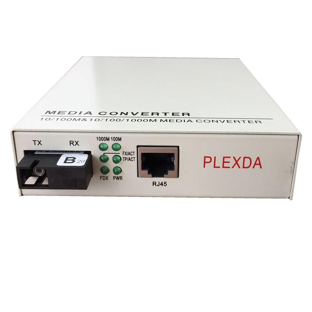
Product
Plexda SFP+, SFP, SFF, QSFP, CFP, Ethernet media converter, POE switch,200G AOC cable OEM factory
Plexda SFP+, SFP, SFF, QSFP, CFP, Ethernet media converter, POE switch,200G AOC cable OEM factory

Tel:0755-28482291
Hotline:13728624948
Local:Home > Product > Fiber Media Converter
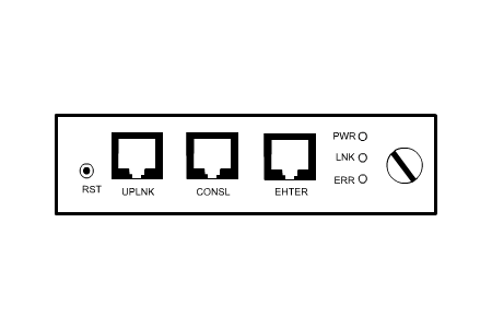
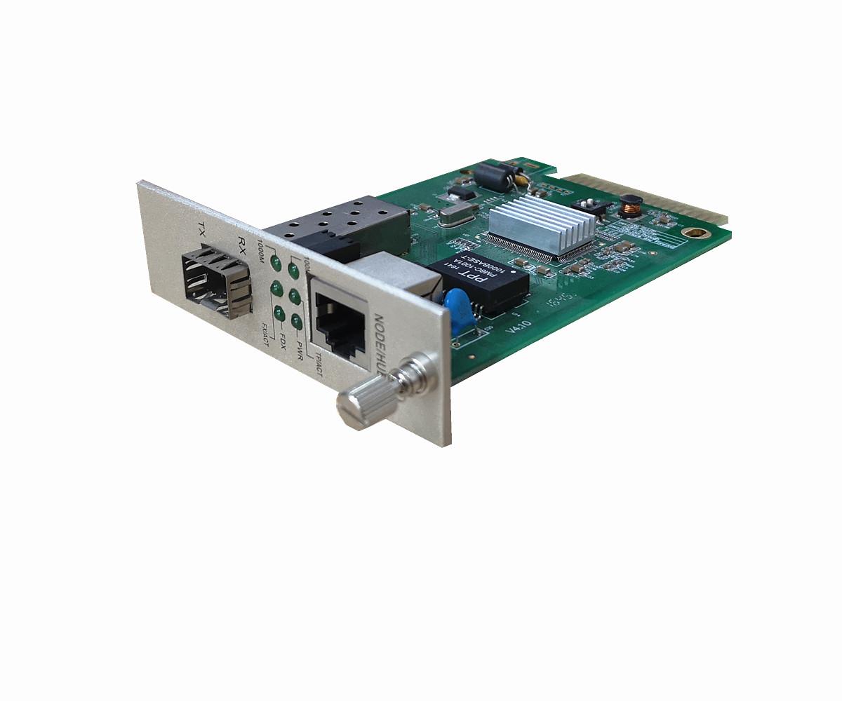
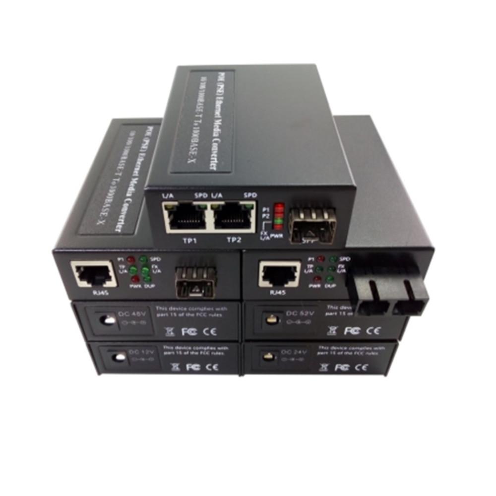
1. Front panel
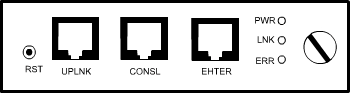
2.Ports:
ETHER:10/100M RJ45connecting to Internet, management center can manage by WEB, SNMP, and TELNET through this port
CONSL : standard RS232 for local CLI management
UPLNK: cascading port
3.LED introduction
LED | color | Indication |
PWR | Green | ON: power normal |
OFF: power abnormal or power down | ||
UPLNK | Green | ON: internet connection normal |
OFF: non-connection to Ethernet | ||
FLASH: data transmission | ||
ERR | Red | ON: abnormal(normal with flash for one time when power on) |
OFF: normal |
4.Buttons introduction
RST: recover to factory default setting
(IP Address 192.168.1.251, Sub mask: 255.255.255.0, Gateway:192.168.1.1)
Notice: Please press RST and insert management card to the chassis when use RST
function. After around 30 minutes, the management card will recover to factory setting.
5. Port connection introduction
5.1 ETHER port: When connect to switch/Hub please use Straight-through cable, when
connect to PC card please use Cross-over cable
5.2 CONSL port: Please use the matched serial cable(RJ45 TO DB9)
5.3 UPLNK port: use standard straight-through or cross-over cable
II. Instruction for Cascading card
1. Front panel
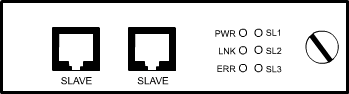
2.Ports:
SLAVE: connect to management card or other cascading card SLAVE : connect to management card or other cascading card Notice: either port is applicable since they have same function.
3.LED introduction:
LED | Color | Definition |
PWR | Green | ON: Normal OFF: abnormal |
LNK | Green | ON: connect to management card |
FLASH: chassis in polling | ||
OFF: Disconnection | ||
ERR | Red | ON: Error, wrong chassis No. |
OFF: normal | ||
SL1 | Green | ON: chassis No. 1 |
SL2 | Green | ON: chassis No. 2 |
SL3 | Green | ON: Chassis No.3 |
4.Cable connection introduction
Communicate with standard RS485 cable, connector RJ45, transmitting distance can rach
1KM, pls use either straight-through cable or cross-over cable to connect the sub card.
5.Switch introduction
There is a switch in the cascading card, used for setting cascading card No.. Please finish above operation before starting power supply.
Notice: When there are more than one cascading cards, each cascading card
should be setting with different numbers, or there will be clash causing wrong data transmission.

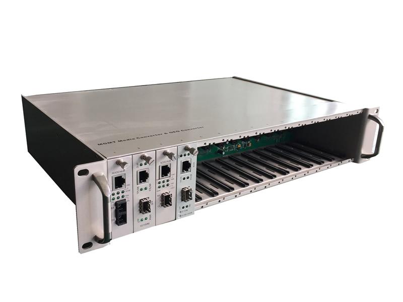
Part Number | Package | Description |
FMC-NMC14 | 2U Card | Media Converter Network Manageable SNMP Card |
FMC-GEBX Series 10/100/1000M Single core WDM Inter...
FMC-GES14-C series 10/100/1000BASE-TX to 1000BASE...
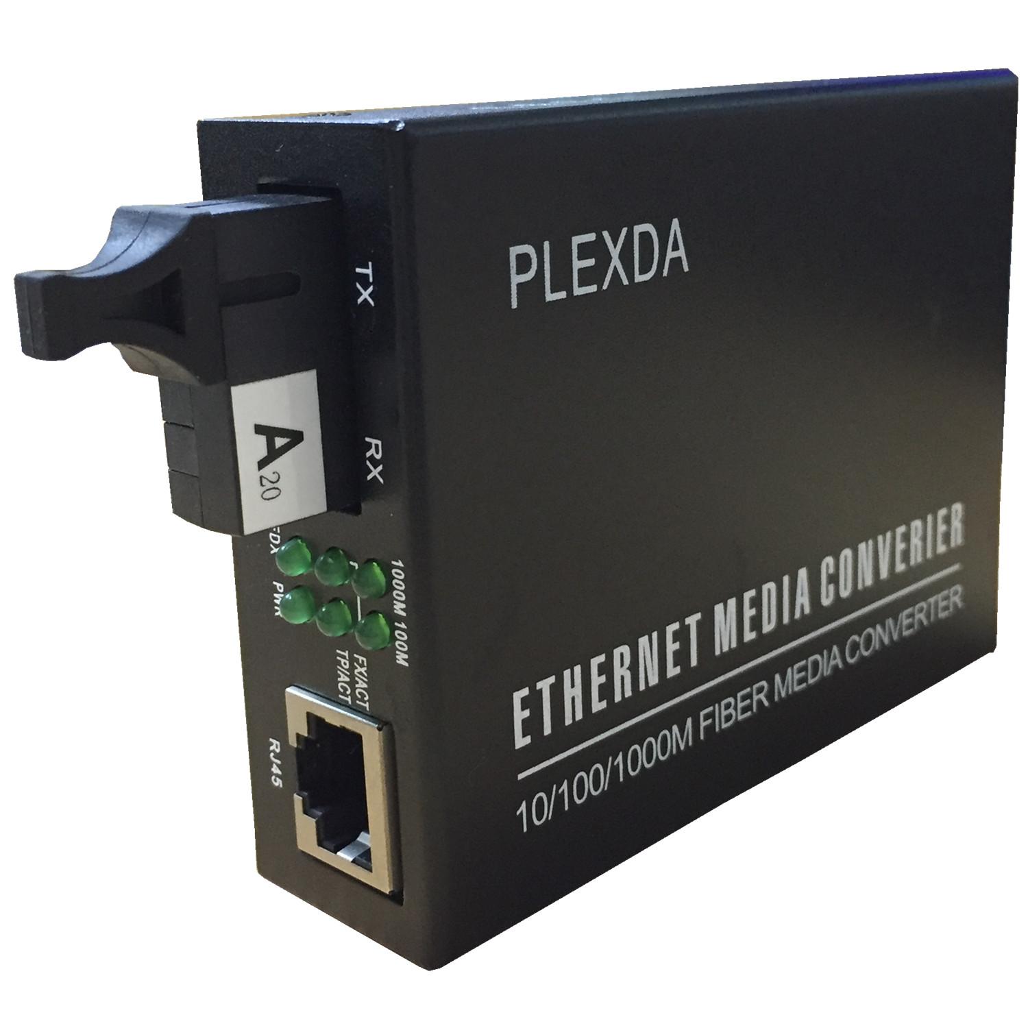
FMC-GEBX-E series 10/100/1000M Single core WDM gi...
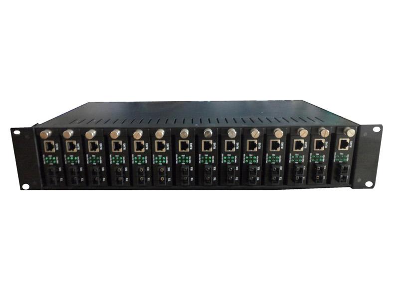
FMC-ERACK-14 14 Slots 2U Rack mount Chassis
FMC-ERACK16 16 Slots 2U Rack Mount Chassis
FMC-GES14-PE 10/100/1000Base-T to 1000Base-X POE (...

 English
 Chinese